
Analog Spindle Inverter Problems (mrw)
Problems:
- Spindle running too slow, too fast
- Spindle drive varishiv not set correctly
- MC2 card settings
- Inverter settings
- Spindle not running at all
- E stop on control or operator station
- Incoming power, or 3 phase disconnect
- Programming problem - ie: MO3 vs M03 or S000 vs S3000
- Inverter problems
- Operator station not plugged in
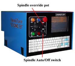
- Spindle override pot
- Spindle Auto/Off switch on control face
- MISC cable not plugged in or defective
- Eratic spindle speeds
- Capacitor on TB1 -TB2
- Bad pot on control panel
- Shutting down with spindle drive fault light coming on
- Spindle speed to slow
- Voltage to low or high
- Braking resistor
- Motor
- Inverter settings - accell or decel to short
- Cycle time and spindle speed
- Programming issues with CSF
- Spindle lock
- Too much mass for the inverter to drive with Accel/Decel setting
- Spindle accell or decel to slowly
- Inverter settings
- Mechanical belt issues
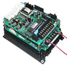
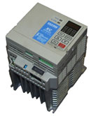
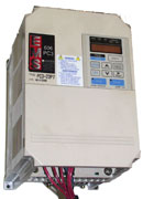
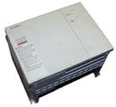
OmniTurn has used different types of spindle drive inverters. Many of the older retrofits used a Yaskawa JustSpeed inverter, or Mitsubishi inverter. Newer machines use the Yaskawa PC-3 inverter. If you are unable to identify your inverter, contact OmniTurn Service.
| Yaskawa S-300
JustSpeed |
Yaskawa Mini | Yaskawa PC-3 | Mitsubishi |
 |
 |
 |
 |
Retrofits / Attachments
Tools required:
- Tachometer
- Adjustable wrench
- Allen wrench
- Volt meter
1. Be sure that your spindle override pot on the control panel is fully clockwise and the Auto-Off switch is in the Auto position.
If the machine is a Hardinge retrofit, the problem is likely to be a maladjustment of the original Vari-drive, or a loose drive belt
- Open the motor cover on both the front and rear of the lathe, and check that the flat belt running on the drive motor pulley has no more than 1-1.5" pinch play (squeeze both sides of the belt together to check). If it's loose, loosen the two locking bolts on the sides of the motor plate, and lower the rear of the plate with the Allen headed lifting bolt in the center.
- Then be sure to re-tighten the lock bolts.
- At the control, in MDI mode, give a M03S1000 command, and measure the rpms with your tach.
If it is still too low, or even too fast by 50 or more RPM, further adjustments are called for.
- Open the front motor compartment door, and look at the Vari-Drive yoke height. It should be within 3 inches of the top of the door frame. On most Hardinge Lathes, you will notice a large Acme lead screw running vertically upwards through the front of the yoke. Turning this lead screw by hand will raise or lower the yoke, making the spindle run faster or slower.
Often, machine vibration cases this lead screw to turn on its own, lowering the yoke and making the spindle run slower. - Have someone tach the spindle, as the machine is running at a programmed 1000 rpm, turn the lead screw and raise the yoke, until the rpms read 1000 +/-.
- Then give it a S3000 command and run the spindle at the 3000 rpm setting. Read the tach and it should be around 3000 rpm. It is rare that both readings at 1000 and 3000 will be exact, but should be within 50-75 rpm of each other.
- Note about setting the MC2 and inverter goes here
- Take an automotive hose clamp and tighten it around the acme leadscrew under the yoke, so the yoke will not move.
Some AHC models used a hydraulic lifter for the yoke, and when you open the front of the motor door, you will see a vertical piece of steel with square cut notches attached to the yoke. There are 2 sliding keepers that allow you to raise or lower the yoke, and then lock the yoke into the proper height. Use a large screwdriver or crowbar and lift the yoke by hand until the proper rpms are found, then lock the yoke into place with those sliding keepers, and be sure to tighten the lock screws on each.
GT-75
Check for proper belt tightness, and check that the motor drive pulley is tight on the shaft. This is keyed and also uses a tightening system, but can come up, check them out.
Check the spindle pulley for the same condition.
All Machines
Open the grey OmniTurn spindle drive cabinet and locate the long terminal strip on the left side of the inverter.
Give a 3000 rpm command, and using your volt meter on DC, check the voltage between terminals 1 and 2. It should read between 9 -10 vdc. If it does not, re-seat the Miscellaneous cable on both ends, checking for pins that have been pushed in too far. If everything looks ok, it generally means your MC-2 card has failed and needs replacement.
This section needs more details on the MC2 card
If the voltage reading is correct, the problem lies elsewhere
Inverter Diagnosis
Yaskawa with Digital display
Turn off the power to the lathe before proceeding!!
Using a screwdriver, make sure all screws and wires are tight
Turn on the control power, and use a wrench to turn on the high voltage to the drive cabinet. Be careful, around the fuses and relays as they now have 208 volts on them.
Check the voltage on L1, L2, and L3 terminals on the inverter. If your shop is wired for 3-phase power, you should see 208 -/+ on each terminal, measured to each other. If one is dead, check for blown fuses or breakers.
If your shop is wired for 220 single phase, L1 & L2, should have 220 VAC +/- across them. If not, check for blown fuse or breaker. If everything looks ok, proceed:
At the control, in MDI mode, give a M03S3000 command.
In the drive cabinet, the digital display on the PC-3 inverter should show 100-120 hz. If it does not, and 9-10 volts appears on terminals 1 & 2 of the terminal strip, the inverter probably has failed .
On the inverter keypad, Press the loc/rem button to put the inverter into local mode. Use the arrow buttons to set the displayed number to 120hz, and press the run button. This should run the spindle at 3000-4000 rpm (depending on the machine style). If the spindle still runs slow, either the inverter or the motor has failed.
Use your volt meter set on 250volts AC and check the voltage at the motor terminals on the inverter. Measured against each other, your reading should be around 200-220VAC. If one terminal is dead, the inverter needs replacement. If all three terminals have the proper voltage, your drive motor needs replacement. Consult the factory for replacement.
JustSpeed, Mitsubishi and Yaskawa PC-3 with no digital display
Each of these units require a separate Programming unit to completely check out, or change programming. See your OmniTurn Dealer or the factory. Diagnosis is identical with the above procedure, but manually operating the inverter requires the proper programmer.
On lathes equipped with these units, and 3-phase power, you may check the motor and possibly eliminate it as a problem.
Remove power to the machine!
Remove the motor wires from the inverter terminals, and using wire nuts and jumper wires, jumper each motor wire to the 3-phase fuse block. Be sure the fuses are good.
Turning on the high voltage should run the drive motor at its rated rpm IE, usually 1750 RPM measured at the motor. If the motor runs very slow, or not at all, it needs replacement.
If you have single phase power only, there is no way to test the motor. An OmniTurn Service Tech should be called.
NOTE:
If it is determined that a JustSpeed, Mitsubishi or PC-3 with no Digital Display Inverter has failed, we only offer the PC-3 Digital Display as a replacement. Wiring will be slightly different, so ask your OmniTurn Dealer for the proper conversion diagram if you intend to install it yourself.
|
|
 |
|||||||||||||||||