Items that can effect the RPM
- MC2 card rpm Min and Max adjustment pots - The MC2 card has a pot to set the min and max speeds. The control "talks" to the spiindle drive by putting out a reference voltate, 0 - 10V DC. At 0V the spindle should be at rest. At 10V the drive should put out max RPM. Setting MC2 card voltages
- Inverter parameters - The inverter has parameters that effect the max speed. See the inverter manual or talk to a tech if this is an issue.
- Software limit in OmniTurn control - The OmniTurn control has a software parameter that sets the max rpm. This is the rpm that will put out 10V. If the parameter is set for 4000 rpm the control will put out 10V whenever 4000 rpm or higher is requested.
- Pot on the front panel of the control - Remember the pot that is on the front panel of the control. If your RPM is messed up, make sure the pot is turned full CW.
- Up / Down arrow keys on keyboard - The up down arrow keys can be used to adjust the rpm in 10% increments. If the arrow keys have been used the spindle speed can be off from what you think it should be. To be sure press the 7 (Home) key on the numeric key pad portion of the keyboard. This will reset the arrow key adjustment.
- Pulley ratio on spindle motor - attachment issue only. Of course pulley sizes will effect the rpm output. Contact your OmniTurn tech for assitance re this issue.
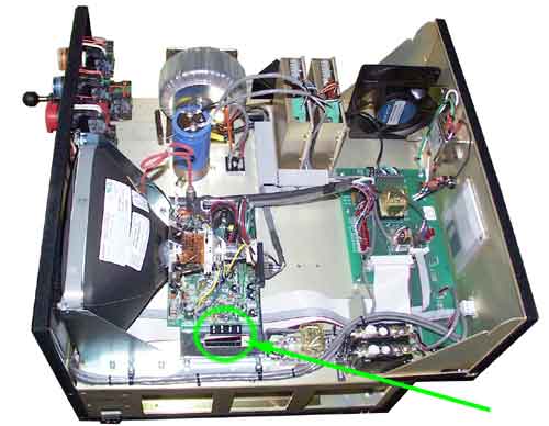
See photo below. This is where the pots are on the newer (G3) controls. On the older A and G2 controls the pots can be seen from the side of the control, they would be in the lower half facing the right side of the control. All else is the same for the rest of the instructions.
There are 4 pots, the front 2 are for part of the axis servo amp ajustments. Do not touch these. The 2 back ones are marked as adjustment for min and max. After this photo are the next instructions.

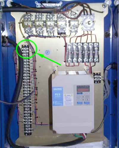
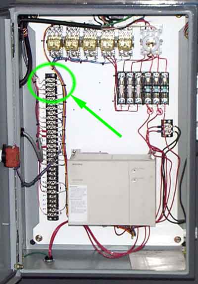
Put your meter on TB1-1 and TB1-2. These contracts are in the spindle drive cabinet. Below are photos of two cabinet types showing the location of the contacts. They are the top two and usually have a capacitor tied between them. If there is no capacitor, check with a tech, you should add one. There should be 0V at this point. If not, then adjust the min pot on the MC2 card.
With min set, request max rpm, ie M03S4000 and the voltage should be 10V. If not adjust the other pot on the MC2.


